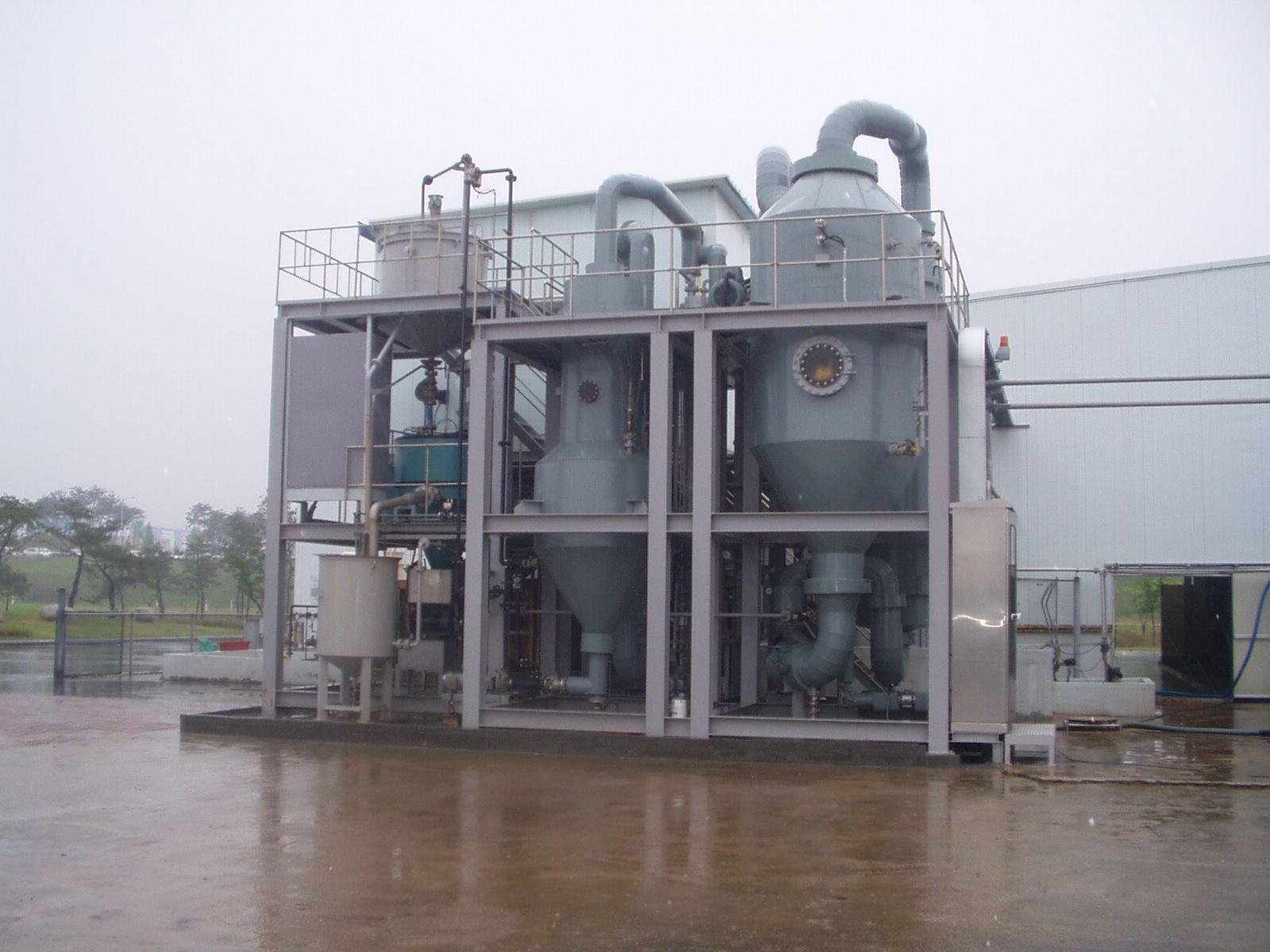
MVR evaporation and crystallization plant
Water & process plants,
optimized in 3D.

Water Reuse & Treatment Process Design and 3D Plant Engineering

PlanET DNS Co., Ltd. is an environmental engineering company specializing in water reuse and water treatment. We provide raw water analysis and mass balance, basic and detailed design, 3D plant design, fabrication, commissioning, and pilot-scale demonstration and research services for wastewater reuse, process water, brine treatment, crystallization, and battery material processes.

PlanET at a Glance

Since2017Design, fabrication & engineering services
Records42Completed projects
Patents7Patents held & invented
3D Plant Design

3D Model-Based Design Review and Fabrication Drawings

Tanks, membranes, pumps and piping are modeled in Autodesk Inventor to review clashes, maintenance access and pipe routing. Quantities and fabrication drawings are taken directly from the model, minimizing deviation between design and fabrication.

01Clash Review

Equipment, piping and steel clashes are resolved at the design stage to minimize rework on site.

02Quantity Take-off

Material quantities are extracted from the 3D model for more accurate cost estimation.

03Drawing Production

Fabrication, assembly and layout drawings are generated from the 3D model.

04O&M Review

Operator access and maintenance space are reviewed with the client in advance.

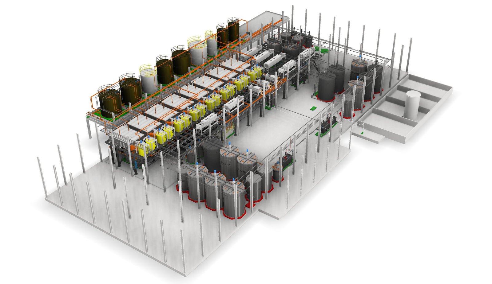
Full 3D assembly model of battery material recycling process
Battery Material Recycling Process Expansion WorksLeaching · Solvent extraction · Equipment + steel + piping
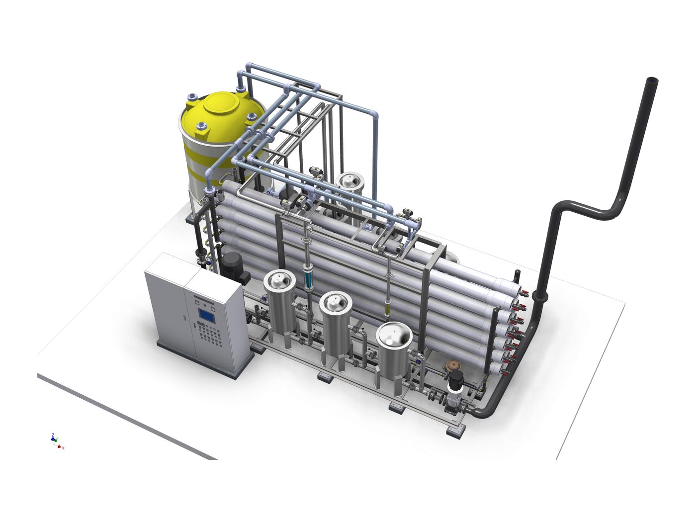
3D model of RO process water system
RO Process Water System2-pass reverse osmosis · Skid
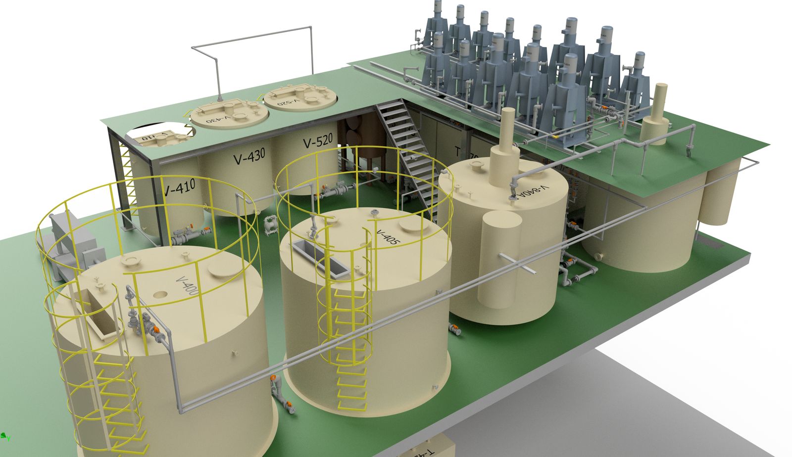
3D rendering of upper reactor deck
Reactor DeckHandrails · Stairs · Piping
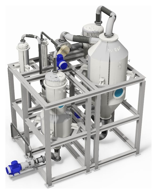
3D model of evaporation system
Evaporation SystemMVR Evaporator
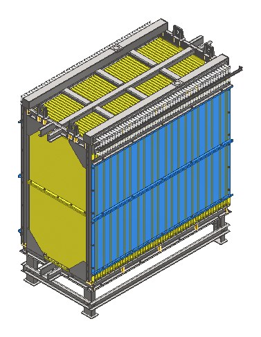
3D model of MBR module frame
MBR FrameMembrane module support frame
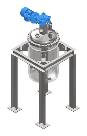
3D model of jacketed agitated reactor
Agitated ReactorChemical process reactor
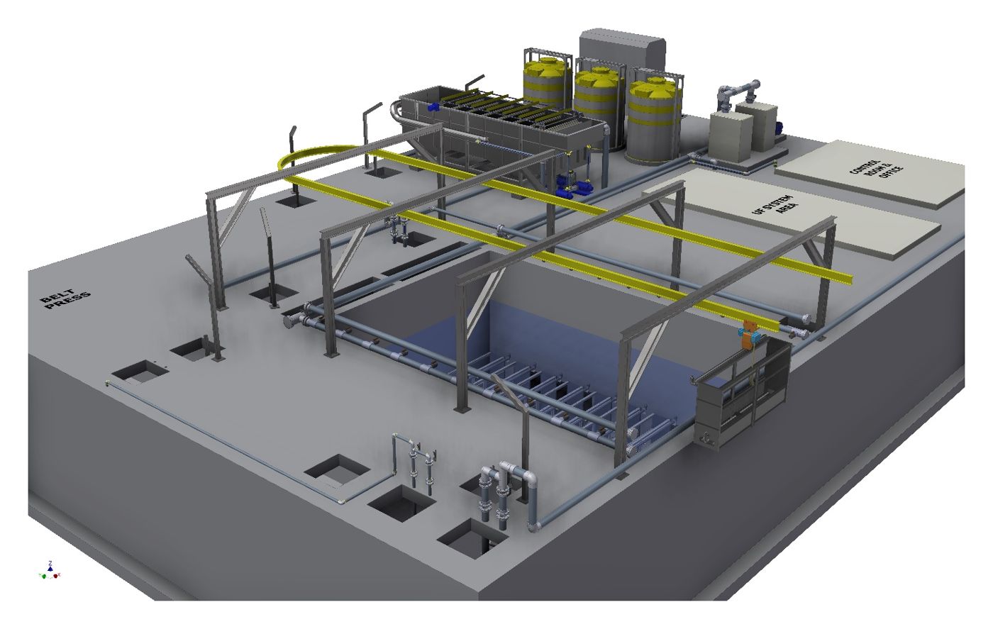
3D model of wastewater treatment facility
Wastewater TreatmentDAF + MBR
Design Scope

Single equipment · Skid packages (UF·RO·EDI) · Reactors & tanks · Steel structures, platforms & handrails · Pipe routing · Plant layout · Structural review interface

Tools

Autodesk Inventor Professional (Tube & Pipe) · AutoCAD · Navisworks

Capabilities

Scope of Services

We deliver process design, 3D design, fabrication, installation and commissioning as one continuous scope. Pilot demonstration and research projects (R&D) are carried out as a separate service.

Water Reuse SystemsSewage & wastewater reuse, greywater & rainwater reuse, process water, brine treatmentUF · RO · EDI · Evaporation
3D Plant DesignInventor-based modeling of equipment, steel and piping; plant layout designClash review · Quantity take-off · Fabrication drawings
Water Treatment Process DesignRaw water analysis · Mass balance · PFD/P&ID · Basic & detailed designDrinking water · Sewage · Wastewater · Reuse
Physicochemical TreatmentHybrid Jet Mixer coagulation · DAF · Lamella settling · Phosphorus removalCoagulation · Flotation · Settling · Filtration
Biological TreatmentMBR · SBR · AGS · Biofilm carrier processesSewage · Domestic · Industrial wastewater
Evaporation · CrystallizationDesign and fabrication of MVR/TVR evaporators and crystallizers · ZLD concept designHigh-strength wastewater · RO brine
Chemical Process EquipmentTanks · Reactors · Filter presses · Mixer-settlersBattery materials · Chemical processes
Mixing & Aeration EquipmentIn-house Hybrid Jet Mixer (patented coagulation mixer) · Mixing, chemical dosing and aeration in a single unitHigher oxygen transfer · Lower power demand · Floc preservation
Pilot · Demonstration · R&DLab- to pilot-scale units, verification of new environmental technologies, research projectsLab-to-pilot design & fabrication

  1. Process Design
  2. 3D Design
  3. Fabrication
  4. Installation · Commissioning
Our Business

Water Treatment Technologies

Membrane filtration, physicochemical, biological and evaporation processes are evaluated and combined according to raw water characteristics and treatment targets.

WATER REUSE · MF / UF / RO / EDI

Wastewater Reuse and Process Water Production

Treated sewage, process wastewater and rainwater are treated by UF and RO for reuse as industrial and process water. By combining RO with ion exchange or EDI, ultrapure water of 15 MΩ·cm or higher can be produced.

Process Units · Design Points
  • MF·UF Membrane FiltrationReduces SDI and turbidity to protect downstream RO from foulingPretreatment
  • Reverse Osmosis (1- and 2-stage arrays)Array and flux design based on target recovery and concentrate LSIDesalination
  • EDI · Ion ExchangePolishing of RO permeate to 15 MΩ·cm or higherUltrapure water
  • CO₂ Control · DegassingpH and alkalinity adjustment to suppress CaCO₃ scalingScale control
  • CIP SystemChemical cleaning sequences for organic fouling and inorganic scaleMembrane recovery
  • Product Water Storage · SupplyRecirculation to prevent recontamination during storageSupply
Technology Development · High-Recovery Reuse

Developing High-Recovery Reuse of Treated Sewage Effluent

Conventional UF–RO reuse plants are limited to about 80% recovery by CaSO₄, CaCO₃ and SiO₂ scaling. We first remove scale-forming species by crystallization and precipitation, recover more water with additional RO stages, and treat the remaining concentrate with NF and MVR crystallization. The process is designed as a retrofit to existing plants, with AI-assisted operation.

≥95%Target net RO recovery (conventional UF–RO ≈ 80%)
−77%RO residual liquid 4.0 → 0.9 m³/h (preliminary balance)
≥5%Target reduction in energy and chemical use with AI-assisted operation
01

Feed · Pretreatment

Effluent → (if needed) BAC/DNF → UF

Inflow 20.000
02

Primary Reuse

CO₂ water quality control → RO-1

Permeate 15.960
03

Scale Control

CO₂ stripping → CaCO₃·CaSO₄ seeded FBC → Mg-based SiO₂ removal

Ca ≥60% · SiO₂ ≥80%
04

High-Recovery RO

RO-2 → RO-3, inter-stage FBC crystallization when scaling occurs

Add'l permeate 3.132
05

Selective NF

Separation of sulfate and chloride streams

Treated 0.778
06

Concentration · Crystallization

MVR evaporation → crystallization → condensate recovery

Condensate 0.739

Flows in m³/h. Preliminary mass balance for an example feed of 20 m³/h.

A · Baseline

Conventional UF–RO

Reuse water
16.000
Residual liquid
4.000

Current concentrate treatment and discharge

B · Priority for commercialization

High-Recovery MLD

Reuse water
19.092
Residual liquid
0.908
10-yr NPV (assumed)
+KRW 51M

Additional recovery in RO-2/3 after FBC and SiO₂ reduction; 24,736 m³/yr additional water

C · Conditional

NF–ZLD

Potential reuse water
19.831
Final discharge
0.169
10-yr NPV (assumed)
−KRW 1.284B

Considered where concentrate disposal costs exceed about KRW 8,427/m³

Industrial Water SecuritySecures industrial water without developing new sources.
Concentrate ReductionLowers discharge and off-site disposal costs along with membrane fouling risk.
Total Pollutant Load ManagementMeasured net BOD and T-P discharge supports load-reduction negotiations with local authorities.
Aquatic Ecosystem BalanceReuse volume is set with instream flow requirements in mind.

All figures are preliminary mass balances and research targets for an example feed of 20 m³/h, to be confirmed through demonstration. Economics assume 8,000 operating hours per year, alternative water at KRW 1,500/m³, concentrate treatment at KRW 3,000/m³, a 5% discount rate, and capital costs of KRW 500M (B) and KRW 1.5B (C). Related core technology: Korean Patent No. 10-3006469 (Method and apparatus for reusing treated effluent). Demonstration follows a 36-month, three-stage Go/No-Go plan.

Technology Development · Patented Coagulation Mixer

Hybrid Jet Mixer

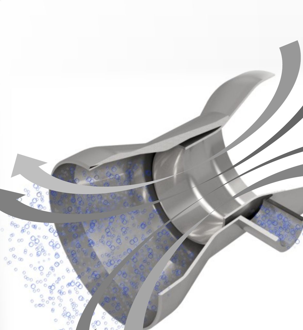
As fluid passes through the converging–diverging Jet Conical Impeller (JCI), its velocity increases and its pressure drops. Using this Venturi effect, a single unit performs mixing, chemical dosing and aeration.

Cross-section of the Jet Conical Impeller and flow direction: fluid enters the converging section, passes the throat and discharges through the diverging section with fine bubbles
Flow Through the JCIAcceleration in converging section → low pressure at throat → discharge and bubble breakup
3.1–3.5×Oxygen transfer coefficient KLa
vs. membrane diffusers
Self-AspiratingLow pressure at the throat draws in air
and chemicals without extra power
Low-Speed OperationComparable mixing at 100–300 rpm
(CFD analysis) · Lower power demand
Mixing ↔ AerationSwitch processes in one unit
by opening or closing the air inlet
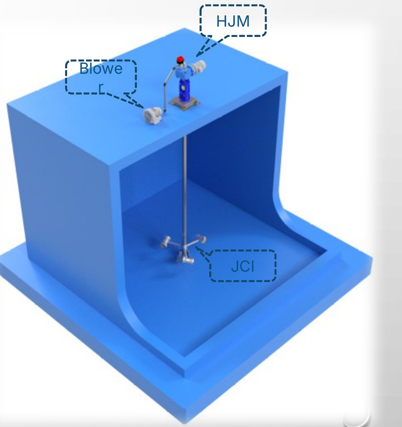
Hybrid Jet Mixer aeration system: HJM drive and blower above the tank, JCI submerged
Aeration System LayoutHJM drive · Blower · Submerged JCI
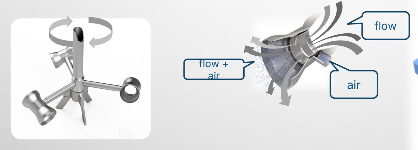
Three-branch JCI impeller with flow, air and flow+air paths
Air–Liquid Mixing PathAir intake + flow → JCI → flow+air discharge
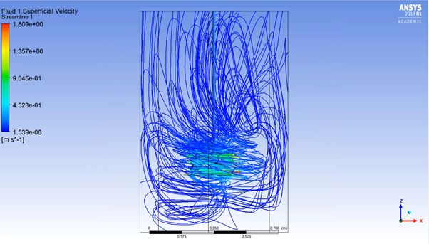
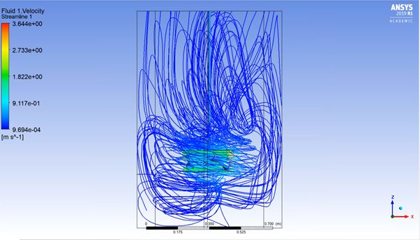
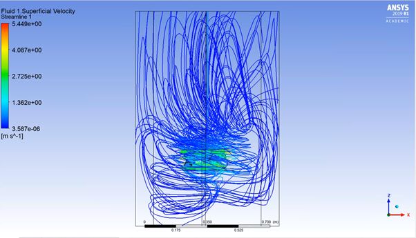
CFD 100 rpmCFD 200 rpmCFD 300 rpm
CFD Flow AnalysisComparable mixing flow at 100 · 200 · 300 rpm
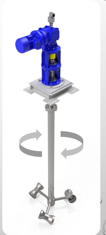
Hybrid Jet Mixer unit: gear motor, hollow shaft and three-branch JCI
Mixer UnitGear motor · Hollow shaft · 3-branch JCI
How it works

Operating Principle

  1. AccelerationFluid entering the JCI is accelerated through the converging section, adding kinetic energy to the discharge for flow-driven mixing.
  2. SuctionPressure drops at the throat, drawing air or chemicals through the hollow shaft for immediate rapid mixing inside the JCI.
  3. DispersionVelocity changes in the diverging section create turbulence that breaks air into fine bubbles.
  4. RetentionRotational flow slows bubble rise, extending gas–liquid contact time.
Measured effect

Oxygen Transfer Coefficient KLa

ConditionHybrid (hr⁻¹)Diffuser (hr⁻¹)Ratio
Tap Water250.270.923.5×
MLSS 3,000206.466.243.1×
MLSS 6,000183.259.763.1×

Oxygen transfer tests of the Hybrid Jet Mixer vs. membrane diffusers (linear regression R² 0.99). The advantage stays above 3× as sludge concentration increases.

Versus conventional

Compared with Conventional Mixer + Diffuser Systems

ItemConventional mixer + blower diffusersHybrid Jet Mixer
MixingRelies on impeller torqueFlow-driven mixing with kinetic energy added by JCI acceleration; open design with low friction loss
Air supplyBlower forces air against water headDrawn in at the low-pressure throat, reducing air supply power
Chemical mixingDosed separately, relies on diffusionDosed through the hollow shaft and flash-mixed in the JCI, minimizing reaction time
Bubbles · Mass transferBubbles rise immediatelyFine bubbles from diverging-section turbulence; rise delayed by rotational flow
Biological flocHigh-speed mixing breaks flocLow-speed rotation minimizes bio-floc breakage
OperationMixer and diffusers operated separatelyMixing and aeration switched in one unit; suited to variable SBR cycles
Applications
  • Chemical Reaction TanksRapid mixing for coagulation and neutralization
  • BioreactorsAeration and dissolved oxygen supply
  • SBRFill → mix/aerate → settle → decant
  • Viscous · Particulate ChemicalsOpen design with low clogging
  • Up Stream FilterFloating media + air backwashing
Track Record

Design, Fabrication and Research Projects

42 projects completed since 2017, including process water systems for food and cosmetics plants, a large-scale MBR demonstration plant, apartment rainwater reuse and mine drainage remediation design.

YearClientScope
Patents

Patents

Coagulation mixing apparatus10-2017-0056828 · 2018Holder
Wastewater treatment system10-2014-0016376 · 2014Holder
Apparatus and method for solubilization and reduction of organic waste10-2015-0189713 · 2017Holder
Bio-scrubber10-2016-0157482 · 2016Inventor
Biological sewage treatment facility removing organics and ammonia nitrogen using a biofilm reactor10-2007-0044157 · 2007Inventor
Advanced biological wastewater treatment apparatus using a spiral biofilm reactor10-2007-0112711 · 2007Inventor
Single-train biological sewage treatment facility using a spiral biofilm reactor and bioreactor10-2009-0033522 · 2009Inventor
Method and apparatus for reusing treated effluentKorean Patent No. 10-3006469 · Core technology for high-recovery reuseCore tech
Contact

Technical Review and Project Inquiries

PlanET DNS Co., Ltd.

TEL+82-70-4042-5825
FAX+82-31-624-5825
EMAILplanet@planetwater-eng.com
ADDRESS#905, Woosung Techno Park, 17 Imok-ro, Jangan-gu, Suwon-si, Gyeonggi-do, Republic of Korea

Sales & Technical Inquiries

CONTACTWOOSUK NA
TEL+82-10-3042-5825
EMAILplanet@planetwater-eng.com